FAQ
Add questions and answers here. Longer answers should preferably be broken off into their own pages and referenced via a Wiki Link. The ODE mailing list has hosted an active discussion of ODE since late 2001. Many topics not covered on this page have been discussed on the mailing list. Click here to search the mailing list with Google.
Compiling ODE
Where can I get a precompiled library for Visual Studio?
I don't want to/can't get the makefile working with Microsoft Visual C++. How do I compile ODE?
Basically, you create a project, tweak some of the options for the config.h header, add all the cpp files in ode/src/ (except for a few that cause problems) into the project, include the drawstuff files, add all necessary include directories, add opengl32.lib and glu32.lib to the link line, and compile. Detailed instructions can be found in the Building ODE with MSVC6 section.
I've compiled the ODE test programs with Microsoft Visual C++, but when I try to run them I get the error message "could not load accelerators." What am I doing wrong?
Add the resource files "ode/drawstuff/src/resources.rc" and "ode/drawstuff/src/resource.h" to your project.
I get an error during linking, "unresolved external symbol."
Basically, you need to learn how to include more than one source file in your project. This is a very basic thing in programming, the manual will tell you how to do it, as will almost any book on programming that describes your compiler. The short version is, do a "find in files" or grep for the symbol that's unresolved to find out which source file its defined in. Don't include any leading underscores in your search. Then, make sure that file is included in your project. It can be included in one of two ways: either directly, the way you include the source files you've written, or as part of a "dynamic linked library" or "shared library." If you're using Microsoft Visual C++ on windows and you're new to programming, you'll probably have more luck if you ditch the makefile and use the MSVC project.
Is there a working solution for MSVC7?
There are two methods for building ODE using MSVC7 (.NET) - you can use the project files provided in the contrib/msvc7 directory of the ODE distribution, or you can check out the Building ODE with VS.NET recipe that takes a command line approach, which fits more naturally with the expected ODE build process. If you take the project file approach, you may find that you need to do a fair amount of tweaking since it may be out of date with the current ODE code structure. Note that you must have OPCODE installed to build the tri-collider version of the MSVC7 project files. COMMENT: I built ODE today on VS.NET followin the instructions Building ODE with MSVC6, it worked okay. I couldn't build all the samples, but that's only a couple of errors with stdlib etc. I think. I later tried the project files in contrib/msvc7, but they didn't work, I got lots of linker errors.
In MSVC7 i get the error "error LNK2019: unresolved external symbol __ftol2".
Try adding this to the top of ode.ccp:
#if (_MSC_VER >= 1300) && (WINVER < 0x0500)
//VC7 or later, building with pre-VC7 runtime libraries
extern "C" long _ftol( double ); //defined by VC6 C libs
extern "C" long _ftol2( double dblSource ) { return _ftol( dblSource ); }
#endif
Using ODE
I found a bug, how do I get it fixed?
Please report bugs using the SourceForge Bug Tracker. You can also request new features.
I reported a bug/requested a feature and no one has done anything about it. Why not?
Unlike some open-source projects, ODE does not have a core group of regular developers. Additions and improvements depend entirely on contributions from the community. While there have been some problems with this approach in the past, the situation is steadily improving. If you would like to join the cause, start by getting the latest source code (Stable Vs Unstable) and then submit a patch (How to get a patch checked in).
What units should I use with ODE?
- Short Answer: Metric, MKS (Metre-Kilogram-Second), thus your lengths will be expressed in meters, masses in kilograms, and timestep in seconds.
- Slightly Longer Answer: "SI Units" or "The international system of Units", http://physics.nist.gov/cuu/Units/ SI units is the technical term for Meter-Kilogram-Second. By always using SI units in calculations, you'll always get SI units out at the other end; you won't end up with nasty multipliers.
- Longer Answer: technically, ODE doesn't use specific units. You can use anything you wish, as long as you stay consistent with yourself. For example, you could scale all your values by Pi, and everything will be fine. Being consistent with yourself is what SI units *is*; remember though that you multiply everything by pi, then your acceleration will include a pi^2 factor. This only gets uglier as it goes... stick with meters-kilograms-seconds
- Longer, Slightly Sillier, Imperial, Answer: Furlongs per fortnight per hour is a perfectly accurate and meaningful description of linear acceleration, but trying to work out how far you've travelled in three minutes at that acceleration starting at zero gives you a lot of ugly multipliers.
How can I make my actor capsule (capped cylinder) stay upright?
Manually reset the orientation with each frame, use an angular motor, apply torques, use a sphere instead, or (quoting Jon Watte) instead use "a hovering sphere with a ray to 'sense' where the ground is and apply spring forces to keep it at a constant height above ground." See 1, 2, 3 for details.
A HOWTO is being set-up over here: HOWTO upright capsule
How do I simulate a wheeled-vehicle?
Check the "How to build a 4-wheeled vehicle" article.
How do I stop my car from flipping over?
Jon Watte has create an excellent demo called CarWorld. It is a bit dated and will probably not compile against the latest versions of ODE, but should tell you everything you need to know about creating convincing wheeled vehicles in ODE. He also made a more recent and leaner demo called RayCar.
A HOWTO is being set-up here: HOWTO 4 wheel vehicle
Can ODE be used in PS2, Gamecube or XBox games?
Can I use ODE in language X?
ODE bindings exist for many programming languages. See ODE in other languages for details.
Can I save and restore an ODE simulation? Will the resumed simulations always continue identically?
Yes, and yes, but there are many things to take into consideration. See HOWTO save and restore
How do I create an object with mass distributed non-uniformly?
An object with a non-uniform mass acts as though the mass were all accumulated at the center of gravity - except that the rotational inertia tensor is noticably different. I recommend reading the O'Reilly book "Physics for Game Developers" which explains clearly how to compute that tensor.
How do I stop things from rolling off into infinity, or pendulums from swinging forever?
ODE models a universe with frictionless hinges and no rolling friction, so problems like those are fairly common.
See the Damping HOWTO.
My simulation jitters and/or explodes. How do I get a stable simulation?
Please see the HOWTO make the simulation better
How can I implement my collision callback as a C++ member function?
See Collision callback member function
How can I simulate a servo motor?
dReal Gain = 0.1;
dReal MaxForce = 100;

dReal TruePosition = dJointGetHingeAngle(joint);
dReal DesiredPosition = /* whatever */;
dReal Error = TruePosition - DesiredPosition;

dReal DesiredVelocity = -Error * Gain;

dJointSetHingeParam(joint[a], dParamFMax, MaxForce);
dJointSetHingeParam(joint[a], dParamVel, DesiredVelocity);
The Gain and MaxForce parameters can be tuned to get the desired stiffness and strength from the joint.
My wheels are sloppy; they don't stay straight when I turn them.
Assuming that you have already enabled finite rotation mode, and set the correct axis each step, you may be bitten by a problem in the joint angle constraints. If you try to set a stop that's inconsistent (hi < lo, etc), then the setter will silently ignore the data. Thus, if hi and low are set to 0.1, and you want to set them to 0.0, the first call to set hi to 0.0 will fail (beacause lo is 0.1); the call to set lo will succeed, leaving the stops at [0.0,0.1]. The solution is to set the hi, then set the lo, then set the hi again -- this will always work, no matter which direction you're trying to move the stops. Getting a vehicle to behave correctly, including wheel behaviour at high speed, isn't as trivial as expected. Look around for working examples, like Jon Watte's CarWorld and the leaner RayCar. See HOWTO 4 wheel vehicle
How do I come up with the optimum values for the parameters to dHashSpaceSetLevels?
They just really depend on the typical sizes of collidable geom (groups) in your space. Set minlevel and maxlevel such that your full range of geom sizes are encompassed. Say that your largest geoms are of size 41 units (in X or Y or Z dimension) and your smallest are 0.25 units in size. Then your dHashSpaceSetLevels? call should be: dHashSpaceSetLevels?(space, -2, 6) to set the min and max cell sizes to 2^-2 = 0.25 and 2^6=64 (2^6 being the smallest power of 2 that '41' will fit in). It's more important to get the max right than to get the min right, assuming that your tiniest objects don't all clump together in the bottom of a hole. You can be over-generous with these values and just suffer a smidgen of time+space overhead. But if you're too stingy, your collision times start to look decreasingly like O(n) and more like O(n^2).
How do I make my AI apply the correct amount of force to move to a particular position?
Please see the HOWTO thrust control logic page.
I have a model loaded from an obj. How can i associate it with a body?
Create a new body (dBodyCreate) for your object. Then use that body's matrix (see "ODE and Graphics" below) as your model/world matrix when you render. How you do that is entirely dependent on your application or engine.
What is the best way to apply physics to a controllable avatar on a landscape?
This has been discussed several times in the mailing list; can someone post some links?
My trimesh object is falling through the floor!
Trimesh-Plane collision wasn't implemented until after the 0.6 release. You can get it from the Subversion repository while you wait for the next release.
My trimesh object doesn't collide at all!
Try inverting the normals. (FIXME: give more detail)
If you have a wavefront obj file for example. (vertices are defined as v [x y z], and faces as f [v1 v2 v3])
To invert the face normals you have to reorder the vertices of the face:
 original face: f 1 2 3 4
 inverted face: f 1 4 3 2
GLMmodel::glmReverseWinding() can do this for you.
I'm using variable timesteps, and getting odd behaviour!
ODE is made to work with fixed timesteps. It's possible to get it to work with variable timesteps, but not trivial. (No, this editor doesn't know how to)
Why not? For example, think of an object "resting" on the ground. It'll actually stabilize at a small depth into the ground. When step sizes vary, the ideal stable position will change at each step, and thus the object will jitter (and may very well gain energy!)
FIXME: It'd be really nice if someone who implemented it could fill out a HOWTO fixed vs variable timestep
I get "ODE Message 3: LCP internal error, s <= 0 (s=0.0000e+00)"
It happens. It is usually caused by an object ramming into another with too much force (or just the right force). Try decreasing the mass of the object, or changing the timestep. Nevertheless, this won't crash your simulation, so you could ignore it as a warning.
LCP stands for linear complementarity problem (see: [1]), a linear algebra problem of finding two vectors that satisfies a certain set of equations based on a square matrix and a column vector. This problem is quite common in optimization, physics simulation and mathematical programming. ODE uses a method developed by (Cottle & Dantzig 1968) .
My (stacks of) boxes are unstable!
Make sure that you are using a constant timestep. Using a variable timestep will result in varying errors in the solver, causing instability.
Make sure that you are generating enough contacts. Most objects need at least three contacts to be stable - this applies to real-world physics too.
Add a small damping force and torque to each box in each frame. You can do this by taking the velocity (linear or angular) of the box, multiplying by a negative coefficient (-0.02 for example) and adding the result back as force (or torque).
Turn on auto-disable. You may need to increase the threshold slightly.
ODE and Graphics
How do I run the simulation without the graphics or with my own graphics code?
The ODE library itself only provides simulation, not graphics code. The example programs have their own very simple graphics code written in OpenGL. To make the example programs simpler, the common graphics code has been split into a very simple graphics library called DrawStuff?. To run ODE without graphics, you want to call dWorldStep?() in a loop. So, read the documentation and look at the example code.
Can I use ODE with DirectX?
Yes, in fact a couple of people already have. Some people say that ODE has one handedness and DirectX another, but that's a myth. ODE doesn't assume any handedness, its only when you hook it up to inputs and outputs that handedness becomes an issue. Microsoft uses left-handed clockwise-winding conventions, which has been used traditionally in computer graphics for a long time (POV-ray is left handed, for example); OpenGL uses right-handed counter-clockwise-winding convetions, which have been used in mathematics and physics for hundreds of years. Which goes to show that the good thing about standards is that there are so many to choose from!
Anyway, here are some ways to convert from ODE to DirectX. As you see, it's very simple -- if you plug in consistent numbers in one coordinate system, and apply all the conventions of that coordinate system, then the numbers you get out are, still, in that coordinate system. The only thing you may need to worry about is triangle winding order; if your mesh uses a winding order that's different from the default for the coordinate system you're using, you need to invert the winding of your triangles.
D3DXVECTOR3 convertVector(const dReal *in)
{
    D3DXVECTOR3 out;

    out.x=(float) in[0];
    out.y=(float) in[1];
    out.z=(float) in[2];

    return out;
}

D3DXQUATERNION convertQuaternion(const dReal *in)
{
    D3DXQUATERNION out;

    out.x=(float)in[1];
    out.y=(float)in[2];
    out.z=(float)in[3];
    out.w=(float)in[0];

    return out;
}

// Second argument can be the value returned by dBodyGetRotation(bodyID)

void convertMatrix(D3DXMATRIX &t, const dReal *bMat)
{
    t._11 = bMat[0];
    t._12 = bMat[1];
    t._13 = bMat[2];
    t._14 = 0;
    t._21 = bMat[4];
    t._22 = bMat[5];
    t._23 = bMat[6];
    t._24 = 0;
    t._31 = bMat[8];
    t._32 = bMat[9];
    t._33 = bMat[10];
    t._34 = 0;
}
- I have been using different matrix conversion code. Somewhere last month I started using above, and somehow the rotations are mirrored. After Lots of testing I found the problem, it was my alterated matrix function (the above one). I got my old one back from a backup, and everything rotated like it should. Here is my version:
void convertMatrix(D3DXMATRIX &t, const dReal *bMat)
{
    t._11 = bMat[0];
    t._12 = bMat[4];
    t._13 = bMat[8];
    t._14 = 0;
    t._21 = bMat[1];
    t._22 = bMat[5];
    t._23 = bMat[9];
    t._24 = 0;
    t._31 = bMat[2];
    t._32 = bMat[6];
    t._33 = bMat[10];
    t._34 = 0;
}
I hope this might help someone.
From D3DXMATRIX to an ODE matrix
I had quite some problems with my matrices. Seems like this fixed it. It converts a D3DXMATRIX rotation matrix to a 3x3matrix for ODE:
dMatrix3 matODE;
matODE[0] = m._13;
matODE[1] = m._12;
matODE[2] = m._11;
matODE[3] = 0.0f;
matODE[4] = m._23;
matODE[5] = m._22;
matODE[6] = m._21;
matODE[7] = 0.0f;
matODE[8] = m._33;
matODE[9] = m._32;
matODE[10] = m._31;
matODE[11] = 0.0f;
The order x,y,z is swapped to z,y,x. I'm not sure if this is needed in every project, but thought I could share it.
Also, Si Brown was kind enough to make his source code available, at http://www.sjbrown.co.uk/buggy.html
I use DirectX, and it seems like ODE has switched to single-precision!
There's also an issue about Direct X autonomously changing the internal FPU accuracy, leading to inconsistent calculations. Direct3D by default changes the FPU to single precision mode at program startup and does not change it back to improve speed (This means that your double variables will behave like float). To disable this behaviour, pass the D3DCREATE_FPU_PRESERVE flag to the CreateDevice call. This might adversely affect D3D performance (not much though). Search the mailing list for details.
To create the device in the right way you could do it in the following way:
//pD3D is asumed to be a valid pointer to a IDirect3D9 structure
pD3D->CreateDevice( D3DADAPTER_DEFAULT , //Use? default graphics card
    D3DDEVTYPE_HAL ,                              /* Hardwareaccelerated?, can be also be
                                                   * D3DDEVTYPE_REF*/
    hWnd,                                         /* handle of the window */
    /*your old value*/ | D3DCREATE_FPU_PRESERVE,  /* ex: D3DCREATE_HARDWARE_VERTEXPROCESSING |
                                                   * D3DCREATE_FPU_PRESERVE */
    &PresentationParameter? ,                     /* where PresentationParameter? is a
                                                   * D3DPRESENT_PARAMETERS structure */
    &pReturnedDeviceInterface?);                  /* where pReturnedDeviceInterface? is a pointer
                                                   * to a IDirect3DDevice9 */
How do I handle gravitation and action at a distance (for a 3D space simulation)?
You will need to compute the forces acting on each of your objects and apply them each frame.
ODE Internals
Why is dVector3 the same size as dVector4? Why is a dMatrix not 3x3?
For making it SIMD friendly. i.e 16 byte aligned (there is no SIMD code in there right now, but there may be in the future).
I have a matrix does dBodygetRotation return ABCDEFGHI or ADGBEHCFI ?
That depends on whether you consider yourself row vector, or column vector, convention.
The matrix is actually a 3x4 matrix, with the fourth values being undefined. Those four values live at offset 3, 7 and 11 when indexed as an array, and would contain the translation values if the matrix was a "real" 3x4.
If you consider yourself column vector on the right, it will return ABCxDEFyGHIz, which is row major,
     | A B C |
M =  | D E F |
     | G H I |
which is the reverse of what you'd use in OpenGL (which is also column vector on the right).
If you consider yourself row vector on the left, it will return
ADGxBEHyCFIz, which is column major, which is the reverse of what you'd
use in DirectX (which is also row vector on the left).
Why are ODE's steps so crude?
When trying out ODE, I decided to test the accuracy of its solver over large steps. My test procedure was:
1. Create a world.
2. Create a body in the world.
3. Confirm that the body's position and linear velocity were 0,0,0.
4. Set the world's gravity to 0,0,-10
5. Step the world by 10.
6. Check the position and linear velocity of the body.
Now, as I did this, I ran the equations for this on pencil & paper next to me, and concluded:
New velocity: 0,0,-100 (Determined by gravity*timestep)
New position: 0,0,-500 (Determined by (gravity/2)*(timestep^2))
Checking ODE's results, I saw:
New velocity: 0,0,-100 (Good)
New position: 0,0,-1000 (Double what it should be)
I then verified my calculation by iterating it over 1000 steps of 0.01 and it came to roughly -500.
Next, I checked the source code to see what mechanism it used, and found ODE's internal step function was:
Vel += Force/Mass
Pos += Vel
When it could, more accurately, be:
Pos += ((Force/Mass)/2)*(Timestep^2) + Vel*Timestep
Vel += Force/Mass
Is there a reason that it uses its current method over this integral method?
Why does ODE have a random function? When does randomness ever have a place in physics simulations?
ODE with external Collision Detection Engines
NO ANSWER
And how does ODE compare to SOLID 3.5 (the version used in [Blender])?
NO ANSWER
From the Manual
How do I connect a body to the static environment with a joint?
Use dJointAttach with arguments (body,0) or (0,body).
Does ODE need or use graphics library X ?
No. ODE is a computational engine, and is completely independent of any graphics library. However the examples that come with ODE use OpenGL, and most interesting uses of ODE will need some graphics library to make the simulation visible to the user. But that's your problem.
Why do my rigid bodies bounce or penetrate on collision? My restitution is zero!
Sometimes when rigid bodies collide without restitution, they appear to inter-penetrate slightly and then get pushed apart so that they only just touch. The problem gets worse as the time step gets larger. What is going on?
The contact joint constraint is only applied after the collision is detected. If a fixed time step is being used, it is likely that the bodies have already penetrated when this happens. The error reduction mechanism will push the bodies apart, but this can take a few time steps (depending on the value of the ERP parameter).
This penetration and pushing apart sometimes makes the bodies look like they are bouncing, although it is completely independent of whether restitution is on or not.
Some other simulators have individual rigid bodies take variable sized timesteps to make sure bodies never penetrate much. However ODE takes fixed size steps, as automatically choosing a non-penetrating step size is problematic for an articulated rigid body simulator (the entire ARB structure must be stepped to account for the first penetration, which may result in very small steps).
There are three fixes for this problem:
- Take smaller time steps.
- Increase ERP to make the problem less visible.
- Do your own variable sized time stepping somehow.
How can an immovable body be created?
In other words, how can you create a body that doesn't move, but that interacts with other bodies? The answer is to create a geom only, without the corresponding rigid body object. The geom is associated with a rigid body ID of zero. Then in the contact callback when you detect a collision between two geoms with a nonzero body ID and a zero body ID, you can simply pass those two IDs to the dJointAttach function as normal. This will create a contact between the rigid body and the static environment.
Don't try to get the same effect by setting a very high mass/inertia on the "motionless" body and then resetting it's position/orientation on each time step. This can cause unexpected simulation errors.
Why would you ever want to set ERP less than one?
From the definition of the ERP value, it seems than setting it to one is the best approach, because then all joint errors will be fully corrected at each time step. However, ODE uses various approximations in its integrator, so ERP=1 will not usually fix 100% of the joint error. ERP=1 can work in some cases, but it can also result in instability in some systems. In these cases you have the option of reducing ERP to get a better behaving system.
Is it advisable to set body velocities directly, instead of applying a force or torque?
You should only set body velocities directly if you are setting the system to some initial configuration. If you are setting body velocities every time step (for example from motion capture data) then you are probably abusing your physical model, i.e. forcing the system to do what you want rather than letting it happen naturally.
The preferred method of setting body velocities during the simulation is to use joint motors. They can set body velocities to a desired value in one time step, provided that the force/torque limit is high enough.
Why, when I set a body's velocity directly, does it come up to speed slower when joined to other bodies?
What is likely happening is that you are setting the velocity of one body without also setting the velocity of the bodies that it is joined to. When you do this, you cause error in the system in subsequent time steps as the bodies come apart at their joints. The error reduction mechanism will eventually correct for this and pull the other bodies along, but it may take a few time steps and it will cause a noticeable "drag" on the original body.
Setting the velocity of a body will affect that body alone. If it is joined to other bodies, you must set the velocity of each one separately (and correctly) to prevent this behavior.
Should I scale my units to be around 1.0 ?
Say you need to simulate some behavior on the scale of a few millimeters and a few grams. These small lengths and masses will usually work in ODE with no problem. However occasionally you may experience stability problems that are caused by lack of precision in the factorizer. If this is the case, you can try scaling the lengths and masses in your system to be around 0.1..10. The time step should also be be scaled accordingly. The same guideline applies when large lengths and masses are being used.
In general, length and mass values around 0.1..1.0 are better as the factorizer may not lose so much precision. This guideline is especially helpful when single precision is being used.
I've made a car, but the wheels don't stay on properly!
If you are building a car simulation, typically you create a chassis body and attach four wheel bodies. However, you may discover that when you drive it around the wheels rotate in incorrect directions, as though the joint was somehow becoming ineffective. The problem is observed when the car is moving fast (so the wheels are rotating fast), and the car tries to turn a corner. The wheels appear to rotate off their proper constraints as though the "axles" had become bent. If the wheels are rotating slowly, or the turn is made slowly, the problem is less apparent.
The problem is that numerical errors are being caused by the high rotation speed of the wheels. Two functions are provided to fix this problem: dBodySetFiniteRotationMode and dBodySetFiniteRotationAxis. The wheel bodies should have their finite rotation mode set, and the wheel's finite rotation axes should be set every time step to match their hinge axes. This will hopefully fix most of the problem.
How do I make "one way" collision interaction
Suppose you need to have two bodies (A and B) collide. The motion of A should affect the motion of B as usual, but B should not influence A at all. This might be necessary, for example, if B is a physically simulated camera in a VR environment. The camera needs collision response so that it doesn't enter into any scene objects by mistake, but the motion of the camera should not affect the simulation. How can this be achieved?
To solve this, attach a contact joint between B and null (the world), then set the contact joint's motion fields to match A's velocities at the contact point. See the demo_motion.cpp sample distributed with ODE for an example.
The Windows version of ODE crashes with large systems
ODE with dWorldStep requires stack space roughly on the order of O(n)+O(m2), where n is the number of bodies and m is the sum of all the joint constraint dimensions. If m is large, this can be a lot of space!
Unix-like operating systems typically allocate stack space as it is needed, with an upper limit that might be in the hundreds of Mb. Windows compilers normally allocate a much smaller stack. If you experience crashes when running large systems, try increasing the stack size. For example, the MS VC++ command line compiler accepts the /Stack:num flag to set the upper limit.
Another option is to switch to dWorldQuickStep.
My simple rotating bodies are unstable!
If you have a box whose sides have different lengths, and you start it rotating in free space, you should observe that it just tumbles at the same speed forever. But sometimes in ODE the box will gain speed by itself, spinning faster and faster until it "explodes" (disappears off to infinity). Here is the explanation:
ODE uses a first order semi-implicit integrator. The "semi implicit" means that some forces are calculated as though an implicit integrator is being used, and other forces are calculated as though the integrator is explicit. The constraint forces (applied to bodies to keep the constraints together) are implicit, and the "external" forces (applied by the user, and due to rotational effects) are explicit. Now, inaccuracy in implicit integrators is manifested as a reduction in energy - in other words the integrator damps the system for you. Inaccuracy in explicit integrators has the opposite effect - it increases the system energy. This is why systems simulated with explicit first order integrators can explode.
So, a single body tumbling in space is effectively explicitly integrated. If the body's moments of inertia were equal (e.g. if it is a sphere) then the rotation axis will remain constant, and the integrator error will be small. If the body's moments of inertia are unequal then the rotation axis wobbles as momentum is transferred between different rotation directions. This is the correct physical behavior, but it results in higher integrator error. The integrator in this case is explicit so the error increases the energy, which causes faster and faster rotation, causing more and more error - leading to the explosion. The problem is particularly evident with long thin objects, where the 3 moments of inertia are highly unequal.
To prevent this, do one or more of the following:
- Make sure freely rotating bodies are dynamically symmetric (i.e. all moments of inertia are the same - the inertia matrix is a constant times the identity matrix). Note that you can still render and collide with a long thin box even though it has the inertia of a sphere.
- Make sure freely rotating bodies don't spin too fast (e.g. don't apply large torques, or supply extra damping forces).
- Add extra damping elements to the environment, e.g. don't use bouncy collisions that can reflect energy.
- Use smaller timesteps. This is bad for two reasons: it's slower, and ODE currently only has a first order integrator so the added accuracy is minimal.
- Use a higher order integrator. This is not yet an option in ODE.
In the future I may add a feature to ODE to modify the rotational dynamics of selected bodies so that they exhibit no rotational error with ODEs integrator.
My rolling bodies (e.g. wheels) sometimes get stuck between geoms
Consider a system where rolling bodies roll over an environment made up of multiple geometry objects. For example, this might be a car driving over a terrain (the rolling bodies are the wheels). If you find that the rolling bodies mysteriously come to a stop when they roll from one geometry object to another, or when they receive multiple contact points, then you may need to use a different contact friction model. This section explains the problem and the solution.
The Problem
An example of such a system is shown in figure 13, which shows a ball that has just rolled down a ramp and touched the ground.
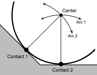
Figure 13: A problem with rolling contact.
Normally, the ball should continue rolling along the ground, towards the right. However, if ODE's default contact friction mode is being used then the ball will come to a complete stop when it hits the ground. Why?
ODE has two ways to approximate friction: the default way (called the constant-force-limit approximation, or "box friction") and an improved way (called "friction pyramid approximation 1") which is obtained by setting the dContactApprox1 flag in the contact joint's surface mode field.
Consider the above picture. There are two contact points, one between the ball and the ramp, the other between the ball and the ground. If the box friction mode is used in both contacts and the mu parameter is set to dInfinity then the ball can not slip against the ramp or ground at either contact.
If no slip is possible at a ball contact point, then the center of the ball must move along a path that is an arc around the contact point. Thus the center of the ball is required to simultaneously move along the path "Arc 1" and "Arc 2". The only way to satisfy both paths at once is for the ball to stop moving altogether.
This is not a bug in ODE - so what is going on here? Objects in real life do not get stuck like this. The problem is that, in the simple "box" approximation of friction the tangential force available at a contact constraint to stop it slipping is independent of the normal force that prevents penetration. This is not real-life physics, so we should not be surprised that non-real-life motion results.
Note that this problem does not occur if mu is set to zero, but this is not a helpful solution because we need some amount of friction to model the real world.
The Solution
The solution is to use the dContactApprox1 flag in the contact's surface mode field, and set mu to some appropriate value between 0 and infinity. This mode ensures that there will only be a tangential anti-slipping force at the contact point if the contact normal force is nonzero. In the above example it turns out that contact-1 will have a zero normal force, so there will be no force applied at contact-1 at all, and the problem is solved! (the ball will roll along the ground properly.)
The dContactApprox1 mode may not be appropriate in all situations, which is why it is optional. It is important to remember that, although it is a better friction approximation, it is not true Coulomb friction. Thus it is still possible that you may encounter some examples of non-physical behavior.
How do i simulate "perfect" bounciness?
If I create 4 planes, and use the Plane2D Joint to restrict movement to the XY 2d plane, than add a box between the planes and give it a velocity, after 4-5 bounces it looses all its energy. I tried setting mu to zero and the surface.bounce parameter to 1, even setting soft_cfm to 1, but still the same results. I tried re-setting the velocity of the object every step like :
const dReal *speed = dyn_bodies[0].getLinearVel();
dReal len = sqrt(speed[0]*speed[0] + speed[1]*speed[1]); // speed_length
dReal sx = speed[0] / len; // get a normalized speed_direction
dReal sy = speed[0] / len;
dyn_bodies[0].setLinearVel(sx*2, sy*2,0);   // fix speed_vector length
...but than it would behave very unrealistically / strange. Also, no gravity is involved.
Known Issues
- When assigning a mass to a rigid body, the center of mass must be (0,0,0) relative to the body's position. But in fact this limitation has been in ODE from the start, so we can now regard it as a "feature" :)