Manual: Joint Types and Functions
Contents |
Creating and Destroying Joints
dJointID dJointCreateBall (dWorldID, dJointGroupID);
dJointID dJointCreateHinge (dWorldID, dJointGroupID);
dJointID dJointCreateSlider (dWorldID, dJointGroupID);
dJointID dJointCreateContact (dWorldID, dJointGroupID, const dContact *);
dJointID dJointCreateUniversal (dWorldID, dJointGroupID);
dJointID dJointCreateHinge2 (dWorldID, dJointGroupID);
dJointID dJointCreatePR (dWorldID, dJointGroupID);
dJointID dJointCreatePU (dWorldID, dJointGroupID);
dJointID dJointCreatePiston (dWorldID, dJointGroupID);
dJointID dJointCreateFixed (dWorldID, dJointGroupID);
dJointID dJointCreateAMotor (dWorldID, dJointGroupID);
dJointID dJointCreateLMotor (dWorldID, dJointGroupID);
dJointID dJointCreatePlane2D (dWorldID, dJointGroupID);
dJointID dJointCreateDBall (dWorldID, dJointGroupID);
dJointID dJointCreateDHinge (dWorldID, dJointGroupID);
dJointID dJointCreateTransmission (dWorldID, dJointGroupID);
Create a new joint of a given type. The joint is initially in "limbo" (i.e. it has no effect on the simulation) because it does not connect to any bodies. The joint group ID is 0 to allocate the joint normally. If it is nonzero the joint is allocated in the given joint group. The contact joint will be initialized with the given dContact structure.
void dJointDestroy (dJointID);
Destroy a joint, disconnecting it from its attached bodies and removing it from the world. However, if the joint is a member of a group then this function has no effect - to destroy that joint the group must be emptied or destroyed.
dJointGroupID dJointGroupCreate (int max_size);
Create a joint group. The max_size argument is now unused and should be set to 0. It is kept for backwards compatibility.
void dJointGroupDestroy (dJointGroupID);
Destroy a joint group. All joints in the joint group will be destroyed.
void dJointGroupEmpty (dJointGroupID);
Empty a joint group. All joints in the joint group will be destroyed, but the joint group itself will not be destroyed.
Miscellaneous Joint Functions
void dJointAttach (dJointID, dBodyID body1, dBodyID body2);
Attach the joint to some new bodies. If the joint is already attached, it will be detached from the old bodies first. To attach this joint to only one body, set body1 or body2 to zero - a zero body refers to the static environment. Setting both bodies to zero puts the joint into "limbo", i.e. it will have no effect on the simulation, but might require some setup work again when re-attaching.
Note : Some joints, like hinge-2 need to be attached to two bodies to work.
void dJointEnable (dJointID);
void dJointDisable (dJointID);
int dJointIsEnabled (dJointID);
Disabled joints are completely ignored during the simulation. Disabled joints don't lose the already computed information like anchors and axes.
void dJointSetData (dJointID, void *data);
void *dJointGetData (dJointID);
Get and set the joint's user-data pointer.
int dJointGetType (dJointID);
Get the joint's type. One of the following constants will be returned:
| dJointTypeBall | A ball-and-socket joint. |
| dJointTypeHinge | A hinge joint. |
| dJointTypeSlider | A slider joint. |
| dJointTypeContact | A contact joint. |
| dJointTypeUniversal | A universal joint. |
| dJointTypeHinge2 | A hinge-2 joint. |
| dJointTypeFixed | A fixed joint. |
| dJointTypeAMotor | An angular motor joint. |
| dJointTypeLMotor | A linear motor joint. |
| dJointTypePlane2D | A Plane 2D joint. |
| dJointTypePR | A Prismatic-Rotoide joint. |
| dJointTypePU | A Prismatic-Universal joint. |
| dJointTypePiston | A Piston joint. |
| dJointTypeDBall | A Double Ball-And-Socket joint. |
| dJointTypeDHinge | A Double Hinge joint. |
| dJointTypeTransmission | A Transmission joint. |
dBodyID dJointGetBody (dJointID, int index);
Return the bodies that this joint connects. If index is 0 the "first" body will be returned, corresponding to the body1 argument of dJointAttach. If index is 1 the "second" body will be returned, corresponding to the body2 argument of dJointAttach.
If one of these returned body IDs is zero, the joint connects the other body to the static environment. If both body IDs are zero, the joint is in "limbo" and has no effect on the simulation.
int dAreConnected (dBodyID, dBodyID);
Utility function: return 1 if the two bodies are connected together by a joint, otherwise return 0.
int dAreConnectedExcluding (dBodyID, dBodyID, int joint_type);
Utility function: return 1 if the two bodies are connected together by a joint that does not have type joint_type, otherwise return 0. joint_type is a dJointTypeXXX constant. This is useful for deciding whether to add contact joints between two bodies: if they are already connected by non-contact joints then it may not be appropriate to add contacts, however it is okay to add more contact between- bodies that already have contacts.
Joint feedback
void dJointSetFeedback (dJointID, dJointFeedback *);
dJointFeedback *dJointGetFeedback (dJointID);
During the world time step, the forces that are applied by each joint are computed. These forces are added directly to the joined bodies, and the user normally has no way of telling which joint contributed how much force.
If this information is desired then the user must allocate a dJointFeedback structure and pass its pointer to the dJointSetFeedback() function. The feedback information structure is defined as follows:
typedef struct dJointFeedback {
    dVector3 f1; // force that joint applies to body 1
    dVector3 t1; // torque that joint applies to body 1
    dVector3 f2; // force that joint applies to body 2
    dVector3 t2; // torque that joint applies to body 2
} dJointFeedback;
During the time step any feedback structures that are attached to joints will be filled in with the joint's force and torque information. The dJointGetFeedback() function returns the current feedback structure pointer, or 0 if none is used (this is the default). dJointSetFeedback() can be passed 0 to disable feedback for that joint. Note that if the feedback structure was set, there is no need to use dJointGetFeedback(), since the structure was defined previously and you can check it after every simulation step. The getter is only useful if more than one piece of code wants to enable a feedback on a specific joint; in that case, you can check first if the
joint already have a feedback, and not set another one - which would disable the first feedback set.
Are the returned values valid?
Issues about weird and inconsistent forces and torques in the feedback structure have been reported to the mailing list (e.g. July 2010, April 2009 February 2009, September 2008). Read this conversation too November 2012.
Apparently "as soon as you have a more or less complex system the feedbacks might produce inappropriate values. The constraints solver doesn't care if the forces are evenly distributed, as long as they produce the correct result (that is, they add up to the proper force when they are all applied to the respective bodies)" (ref).
API design notes
It might seem strange to require that users perform the allocation of these structures. Why not just store the data statically in each joint? The reason is that not all users will use the feedback information, and even when it is used not all joints will need it. It will waste memory to store it statically, especially as this structure could grow to store a lot of extra information in the future.
Why not have ODE allocate the structure itself, at the user's request? The reason is that contact joints (which are created and destroyed every time step) would require a lot of time to be spent in memory allocation if feedback is required. Letting the user do the allocation means that a better allocation strategy can be provided, e.g simply allocating them out of a fixed array.
The alternative to this API is to have a joint-force callback. This would work of course, but it has a few problems. First, callbacks tend to pollute APIs and sometimes require the user to go through unnatural contortions to get the data to the right place. Second, this would expose ODE to being changed in the middle of a step (which would have bad consequences), and there would have to be some kind of guard against this or a debugging check for it - which would complicate things.
Joint parameter setting functions
Ball and Socket
A ball and socket joint is shown in figure 4.
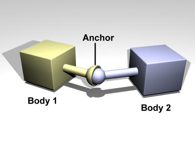
Figure 4: A ball and socket joint.
void dJointSetBallAnchor (dJointID, dReal x, dReal y, dReal z);
Set the joint anchor point. The joint will try to keep this point on each body together. The input is specified in world coordinates. If there is no body attached to the joint this function has not effect.
void dJointGetBallAnchor (dJointID, dVector3 result);
Get the joint anchor point, in world coordinates. This returns the point on body 1. If the joint is perfectly satisfied, this will be the same as the point on body 2.
void dJointGetBallAnchor2 (dJointID, dVector3 result);
Get the joint anchor point, in world coordinates. This returns the point on body 2. You can think of a ball and socket joint as trying to keep the result of dJointGetBallAnchor() and dJointGetBallAnchor2() the same. If the joint is perfectly satisfied, this function will return the same value as dJointGetBallAnchor to within roundoff errors. dJointGetBallAnchor2 can be used, along with dJointGetBallAnchor, to see how far the joint has come apart.
Hinge
A hinge joint is shown in figure 5.
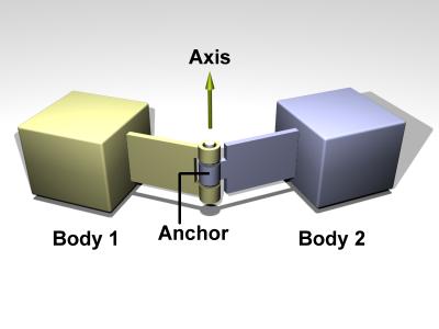
Figure 5: A hinge joint.
The default axis is:
- Axis 1: x=1, y=0, z=0
void dJointSetHingeAnchor (dJointID, dReal x, dReal y, dReal z);
Set hinge anchor parameters. The joint will try to keep this point on each body together. The input is specified in world coordinates. If there is no body attached to the joint this function has not effect.
void dJointSetHingeAxis (dJointID, dReal x, dReal y, dReal z);
Set hinge anchor and axis parameters. If there is no body attached to the joint this function has not effect.
void dJointGetHingeAnchor (dJointID, dVector3 result);
Get the joint anchor point, in world coordinates. This returns the point on body 1. If the joint is perfectly satisfied, this will be the same as the point on body 2.
void dJointGetHingeAnchor2 (dJointID, dVector3 result);
Get the joint anchor point, in world coordinates. This returns the point on body 2. If the joint is perfectly satisfied, this will return the same value as dJointGetHingeAnchor. If not, this value will be slightly different. This can be used, for example, to see how far the joint has come apart.
void dJointGetHingeAxis (dJointID, dVector3 result);
Get hinge axis parameter.
dReal dJointGetHingeAngle (dJointID);
dReal dJointGetHingeAngleRate (dJointID);
Get the hinge angle and the time derivative of this value. The angle is measured between the two bodies, or between the body and the static environment. The angle will be between -pi..pi.
When the hinge anchor or axis is set, the current position of the attached bodies is examined and that position will be the zero angle.
Slider
A slider joint is shown in figure 6.
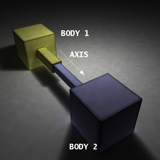
Figure 6: A slider joint.
The default axis is: Axis: x=1, y=0, z=0
void dJointSetSliderAxis (dJointID, dReal x, dReal y, dReal z);
Set the slider axis parameter.
void dJointGetSliderAxis (dJointID, dVector3 result);
Get the slider axis parameter.
dReal dJointGetSliderPosition (dJointID);
dReal dJointGetSliderPositionRate (dJointID);
Get the slider linear position (i.e. the slider's "extension") and the time derivative of this value. If the axis is set such as pointing to Body 0 from Body 1 then the position and rate will be positive has the distance increase between the 2 bodies.
When the axis is set, the current position of the attached bodies is examined and that position will be the zero position.
Universal
A universal joint is shown in figure 7.
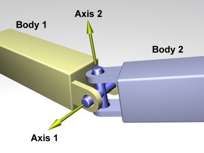
Figure 7: A universal joint.
A universal joint is like a ball and socket joint that constrains an extra degree of rotational freedom. Given axis 1 on body 1, and axis 2 on body 2 that is perpendicular to axis 1, it keeps them perpendicular. In other words, rotation of the two bodies about the direction perpendicular to the two axes will be equal.
In the picture, the two bodies are joined together by a cross. Axis 1 is attached to body 1, and axis 2 is attached to body 2. The cross keeps these axes at 90 degrees, so if you grab body 1 and twist it, body 2 will twist as well.
A Universal joint is equivalent to a hinge-2 joint where the hinge-2's axes are perpendicular to each other, and with a perfectly rigid connection in place of the suspension.
Universal joints show up in cars, where the engine causes a shaft, the drive shaft, to rotate along its own axis. At some point you'd like to change the direction of the shaft. The problem is, if you just bend the shaft, then the part after the bend won't rotate about its own axis. So if you cut it at the bend location and insert a universal joint, you can use the constraint to force the second shaft to rotate about the same angle as the first shaft.
Another use of this joint is to attach the arms of a simple virtual creature to its body. Imagine a person holding their arms straight out. You may want the arm to be able to move up and down, and forward and back, but not to rotate about its own axis.
The default axes are:
- Axis 1: x=1, y=0, z=0
- Axis 2: x=0, y=1, z=0
Note that as the two axes must be perpendicular, an attempt to set the first axis to the value of the second (or vice-versa) will result in an error at runtime even if the second axis is changed immediately afterwards.
Here are the universal joint functions:
void dJointSetUniversalAnchor (dJointID, dReal x, dReal y, dReal z);
Set the joint anchor point. The joint will try to keep this point on each body together. The input is specified in world coordinates. If there is no body attached to the joint this function has not effect.
void dJointSetUniversalAxis1 (dJointID, dReal x, dReal y, dReal z);
void dJointSetUniversalAxis2 (dJointID, dReal x, dReal y, dReal z);
Set universal anchor and axis parameters. Axis 1 and axis 2 should be perpendicular to each other.
void dJointGetUniversalAnchor (dJointID, dVector3 result);
Get the joint anchor point, in world coordinates. This returns the point on body 1. If the joint is perfectly satisfied, this will be the same as the point on body 2.
void dJointGetUniversalAnchor2 (dJointID, dVector3 result);
Get the joint anchor point, in world coordinates. This returns the point on body 2. You can think of the ball and socket part of a universal joint as trying to keep the result of dJointGetBallAnchor() and dJointGetBallAnchor2() the same. If the joint is perfectly satisfied, this function will return the same value as dJointGetUniversalAnchor to within roundoff errors. dJointGetUniversalAnchor2 can be used, along with dJointGetUniversalAnchor, to see how far the joint has come apart.
void dJointGetUniversalAxis1 (dJointID, dVector3 result);
void dJointGetUniversalAxis2 (dJointID, dVector3 result);
Get universal axis parameters.
dReal dJointGetUniversalAngle1 (dJointID);
dReal dJointGetUniversalAngle2 (dJointID);
dReal dJointGetUniversalAngles (dJointID, dReal *angle1, dReal *angle2);
dReal dJointGetUniversalAngle1Rate (dJointID);
dReal dJointGetUniversalAngle2Rate (dJointID);
Get the universal angles and the time derivatives of these values. The angle is measured between a body and the cross, or between the static environment and the cross. The angle will be between -pi..pi.
When the universal anchor or axis is set, the current position of the attached bodies is examined and that position will be the zero angle.
Hinge-2
A hinge-2 joint is shown in figure 8.
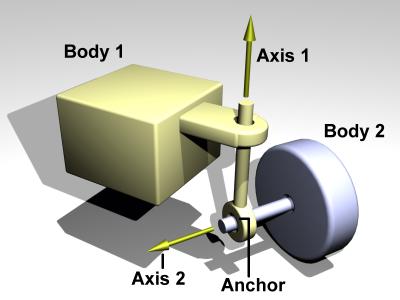
Figure 8: A hinge-2 joint.
The hinge-2 joint is the same as two hinges connected in series, with different hinge axes. An example, shown in the above picture is the steering wheel of a car, where one axis allows the wheel to be steered and the other axis allows the wheel to rotate.
The hinge-2 joint has an anchor point and two hinge axes. Axis 1 is specified relative to body 1 (this would be the steering axis if body 1 is the chassis). Axis 2 is specified relative to body 2 (this would be the wheel axis if body 2 is the wheel).
Axis 1 can have joint limits and a motor, axis 2 can only have a motor.
Axis 1 can function as a suspension axis, i.e. the constraint can be compressible along that axis.
The hinge-2 joint where axis1 is perpendicular to axis 2 is equivalent to a universal joint with added suspension.
Default axes are:
- Axis 1: x=1, y=0, z=0
- Axis 2: x=0, y=1, z=0
void dJointSetHinge2Anchor (dJointID, dReal x, dReal y, dReal z);
Set hinge-2 anchor parameters. The joint will try to keep this point on each body together. The input is specified in world coordinates. If there is no body attached to the joint this function has not effect.
void dJointSetHinge2Axis1 (dJointID, dReal x, dReal y, dReal z);
void dJointSetHinge2Axis2 (dJointID, dReal x, dReal y, dReal z);
Set axis parameters. Axis 1 and axis 2 must not lie along the same line.
void dJointGetHinge2Anchor (dJointID, dVector3 result);
Get the joint anchor point, in world coordinates. This returns the point on body 1. If the joint is perfectly satisfied, this will be the same as the point on body 2.
void dJointGetHinge2Anchor2 (dJointID, dVector3 result);
Get the joint anchor point, in world coordinates. This returns the point on body 2. If the joint is perfectly satisfied, this will return the same value as dJointGetHinge2Anchor. If not, this value will be slightly different. This can be used, for example, to see how far the joint has come apart.
void dJointGetHinge2Axis1 (dJointID, dVector3 result);
void dJointGetHinge2Axis2 (dJointID, dVector3 result);
Get hinge-2 axis parameters.
dReal dJointGetHinge2Angle1 (dJointID);
dReal dJointGetHinge2Angle1Rate (dJointID);
dReal dJointGetHinge2Angle2Rate (dJointID);
Note: There is currently no function call for getting the value of the second angle.
Get the hinge-2 angles (around axis 1 and axis 2) and the time derivatives of these values.
When the anchor or axis is set, the current position of the attached bodies is examined and that position will be the zero angle.
Prismatic and Rotoide
A PR joint is shown in figure 9.
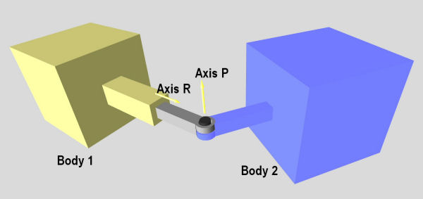
Figure 9: A PR joint.
A prismatic and rotoide joint (JointPR) combines a Slider (prismatic) and a Hinge (rotoide). It can be used to decrease the number of bodies in a simulation. Usually you cannot attach 2 ODE joints together they need a body in between. An example of use of this type of joint can be in the creation of a hydraulic piston.
You can set the position of the body2 with respect to the rotoide articulation by setting the anchor point of this joint. (As for the Hinge joint).
An offset is calculated when the joint is created and this offset is the distance between the body1 and the rotoide articulation. Retrieving the position of the joint will give you the position with respect to this offset.
The first axis is the prismatic axis. Its parameters accessed with the dParamX flag.
The second axis is the rotoide axis. Its parameters can be accessed with the dParamX2 flag.
Default axes are:
- Axis R: x=1, y=0, z=0.
- Axis P: x=0, y=1, z=0
void dJointSetPRAxis1 (dJointID, dReal x, dReal y, dReal z);
void dJointGetPRAxis1 (dJointID, dVector3 result);
Set/Get the axis for the prismatic articulation.
void dJointSetPRAxis2 (dJointID, dReal x, dReal y, dReal z);
void dJointGetPRAxis2 (dJointID, dVector3 result);
Set/Get the axis for the rotoide articulation.
void dJointSetPRAnchor (dJointID, dReal x, dReal y, dReal z);
void dJointGetPRAnchor (dJointID, dVector3 result);
Set PR anchor parameter. The joint will try to keep distance between body2 and the rotoide acticulation fixed. The input is specified in world coordinates. If there is no body2 attached to the joint this function has not effect.
dReal dJointGetPRPosition (dJointID);
Get the PR linear position (i.e. the prismatic's extension)
When the axis is set, the current position of body1 and the anchor is examined and that position will be the zero position.
The position is the "oriented" length between the body1 and and the rotoide articulation.
position = (Prismatic axis) dot_product [(body1 + offset) - (body2 + anchor2)]
Important: The 2 axis must not be parallel. Since this is a new joint only when the 2 joint are at 90deg of each other was fully tested.
Prismatic - Universal
A Prismatic - Universal joint is shown in figure 10.
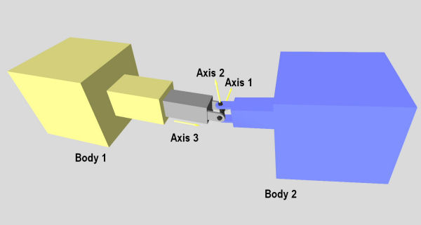
Figure 10: A Prismatic - Universal joint.
A prismatic-Universal joint (JointPU) combines a Slider (prismatic) between body1 and the anchor and a Universal joint at the anchor position. This joint provide 1 degree of freedom in translation and 2 degrees of freedom in rotation.
It was possible to achieve the same result by combining a Slider and a Universal joint but a dummy body was needed between the 2 joints. This joint can be used to decrease the number of bodies in a simulation.
The first axis is the first universal axis. Its parameters accessed with the dParamX1 or dParamX flag (Ex: dParamFMax1).
The second axis is the second universal axis. Its parameters can be accessed with the dParamX2 flag (Ex: dParamFMax2).
The third axis is the prismatic axis. Its parameters can be accessed with the dParamX3 flag (Ex: dParamFMax3).
Default axes are:
- Axis 1: x=0, y=1, z=0.
- Axis 2: x=0, y=0, z=1.
- Axis 3: x=1, y=0, z=0.
dReal dJointGetPUPosition (dJointID);
Get the PU linear position (i.e. the prismatic's extension)
When the anchor is set, the current position of body1 and the anchor is examined and that position will be the zero position (initial_offset) (i.e. dJointGetPUPosition with the body1 at that position with respect to the anchor will return 0.0).
The position is the "oriented" length between the body1 and and the universal articulation (anchor). position = { (Prismatic axis) dot_product [body1 - anchor] } - initial_offset
dReal dJointGetPUPositionRate (dJointID);
Get time derivative of the position.
void dJointSetPUAnchor (dJointID, dReal x, dReal y, dReal z);
void dJointGetPUAnchor (dJointID, dVector3 result);
Set the PU anchor parameter. The joint will try to keep distance between body2 and the universal articulation fixed. The input is specified in world coordinates. If there is no body2 attached to the joint this function has not effect.
void dJointSetPUAnchorDelta (dJointID, dReal x, dReal y, dReal z, dReal dx, dReal dy, dReal dz);
Set the PU anchor and the relative position of each body as if body1 was at its current position + [dx,dy,dy] (dx, dy, dx in world frame).
This is like setting the joint with the prismatic part already elongated or compressed.
After setting the anchor with a delta if the function dJointGetPUPosition is called the answer will be: sqrt(dx*dx + dy*dy + dz*dz) * Normalize[axis3 dot_product (dx,dy,dz)]
void dJointSetPUAxis1 (dJointID, dReal x, dReal y, dReal z);
void dJointGetPUAxis1 (dJointID, dVector3 result);
void dJointSetPUAxis2 (dJointID, dReal x, dReal y, dReal z);
void dJointGetPUAxis2 (dJointID, dVector3 result);
Set/Get universal axis parameters. Axis 1 and axis 2 should be perpendicular to each other.
void dJointSetPUAxis3 (dJointID, dReal x, dReal y, dReal z);
void dJointGetPUAxis3 (dJointID, dVector3 result);
Set/Get the axis for the prismatic articulation.
void dJointSetPUAxisP (dJointID, dReal x, dReal y, dReal z);
void dJointGetPUAxisP (dJointID, dVector3 result);
This is another name for function dJointSetPUAxis3
void dJointGetPUAngles (dJointID, dReal *angle1, dReal *angle2);
dReal dJointGetPUAngle1 (dJointID);
dReal dJointGetPUAngle2 (dJointID);
dReal dJointGetPUAngle1Rate (dJointID);
dReal dJointGetPUAngle2Rate (dJointID);
Get the universal angles and the time derivatives of these values. The angle is measured between a body and the cross, or between the static environment and the cross. The angle will be between -pi..pi.
When the universal anchor or axis is set, the current position of the attached bodies is examined and that position will be the zero angle.
Piston
Piston joint is shown in figure 11.
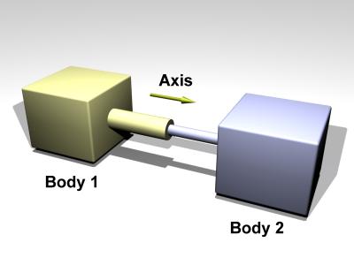
Figure 11: A Piston joint.
A piston joint is similar to a Slider joint except that rotation around the translation axis is possible.
The default axis is: Axis: x=1, y=0, z=0
void dJointSetPistonAnchor (dJointID, dReal x, dReal y, dReal z);
void dJointGetPistonAnchor (dJointID, dVector3 result);
Set piston anchor parameters. The joint will try to keep the distance of this point fixed with respect to body2. The input is specified in world coordinates. If there is no body attached to the joint this function has not effect.
void dJointGetPistonAnchor2 (dJointID, dVector3 result);
Get the joint anchor point, in world coordinates. This returns the point on body 2. If the joint is perfectly satisfied, this will return the same value as dJointGetPistonAnchor. If not, this value will be slightly different. This can be used, for example, to see how far the joint has come apart.
void dJointSetPistonAxis (dJointID, dReal x, dReal y, dReal z);
void dJointGetPistonAxis (dJointID, dVector3 result);
Set/Get piston axis parameters.
When the piston axis is set, the current position of the attached bodies is examined and that position will be the zero angle.
void dJointSetPistonAxisDelta (dJointID j, dReal x, dReal y, dReal z, dReal dx, dReal dy, dReal dz);
dReal dJointGetPistonPosition (dJointID);
dReal dJointGetPistonPositionRate (dJointID);
Get the Piston linear position (i.e. the prismatic's extension)
When the anchor is set, the current position of body1 and the anchor is examined and that position will be the zero position (initial_offset) (i.e. dJointGetPUPosition with the body1 at that position with respect to the anchor will return 0.0).
The position is the "oriented" length between the body1 and and the anchor. position = { (Prismatic axis) dot_product [body1 - anchor] } - initial_offset
dReal dJointGetPistonAngle (dJointID);
dReal dJointGetPistonAngleRate (dJointID);
Get the angle and the time derivative of this value. The angle is measured between the two bodies, or between the body and the static environment. The angle will be between -pi..pi. The only possible axis of rotation is the one defined by the dJointSetPistonAxis.
When the piston anchor or axis is set, the current position of the attached bodies is examined and that position will be the zero angle.
void dJointAddPistonForce (dJointID j, dReal force)
This function create a force inside the piston and this force will be applied on the 2 bodies.
Then force is apply to the center of mass of each body and the orientation of the force vector is along the axis of the piston.
Fixed
The fixed joint maintains a fixed relative position and orientation between two bodies, or between a body and the static environment. Using this joint is almost never a good idea in practice, except when debugging. If you need two bodies to be glued together it is better to represent that as a single body.
void dJointSetFixed (dJointID);
Call this on the fixed joint after it has been attached to remember the current desired relative offset and desired relative rotation between the bodies.
Contact
A contact joint is shown in figure 10.
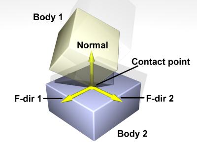
Figure 10: A contact joint.
The contact joint prevents body 1 and body 2 from inter-penetrating at the contact point. It does this by only allowing the bodies to have an "outgoing" velocity in the direction of the contact normal. Contact joints typically have a lifetime of one time step. They are created and deleted in response to collision detection.
Contact joints can simulate friction at the contact by applying special forces in the two friction directions that are perpendicular to the normal.
When a contact joint is created, a dContact structure must be supplied. This has the following definition:
struct dContact {
     dSurfaceParameters surface;
     dContactGeom geom;
     dVector3 fdir1;
};
geom is a substructure that is set by the collision functions. It is described in the collision section.
fdir1 is a "first friction direction" vector that defines a direction along which frictional force is applied. It must be of unit length and perpendicular to the contact normal (so it is typically tangential to the contact surface). It should only be defined if the dContactFDir1 flag is set in surface.mode. The "second friction direction" is a vector computed to be perpendicular to both the contact normal and fdir1.
surface is a substructure that is set by the user. Its members define the properties of the colliding surfaces. It has the following definition:
struct dSurfaceParameters {
     int mode;
     dReal mu;
     dReal mu2;
     dReal rho;
     dReal rho2;
     dReal rhoN;
     dReal bounce;
     dReal bounce_vel;
     dReal soft_erp;
     dReal soft_cfm;
     dReal motion1, motion2, motionN;
     dReal slip1, slip2;
};
- mode - Contact flags. This must always be set. This is a combination of one or more of the following flags:
| dContactMu2 | If not set, use mu for both friction directions. If set, use mu for friction direction 1, use mu2 for friction direction 2. |
| dContactFDir1 | If set, take fdir1 as friction direction 1, otherwise automatically compute friction direction 1 to be perpendicular to the contact normal (in which case its resulting orientation is unpredictable). |
| dContactBounce | If set, the contact surface is bouncy, in other words the bodies will bounce off each other. The exact amount of bouncyness is controlled by the bounce parameter. |
| dContactSoftERP | If set, the error reduction parameter of the contact normal can be set with the soft_erp parameter. This is useful to make surfaces soft.
|
| dContactSoftCFM | If set, the constraint force mixing parameter of the contact normal can be set with the soft_cfm parameter. This is useful to make surfaces soft.
|
| dContactMotion1 | If set, the contact surface is assumed to be moving independently of the motion of the bodies. This is kind of like a conveyor belt running over the surface. When this flag is set, motion1 defines the surface velocity in friction direction 1. |
| dContactMotion2 | The same thing as above, but for friction direction 2. |
| dContactMotionN | The same thing as above, but along the contact normal. |
| dContactSlip1 | Force-dependent-slip (FDS) in friction direction 1. |
| dContactSlip2 | Force-dependent-slip (FDS) in friction direction 2. |
| dContactRolling | Enables rolling/spinning friction. |
| dContactApprox1_1 | Use the friction pyramid approximation for friction direction 1. If this is not specified then the constant-force-limit approximation is used (and mu is a force limit). |
| dContactApprox1_2 | Use the friction pyramid approximation for friction direction 2. If this is not specified then the constant-force-limit approximation is used (and mu is a force limit). |
| dContactApprox1_N | Use the friction pyramid approximation for spinning (rolling around normal). |
| dContactApprox1 | Equivalent to dContactApprox1_1, dContactApprox1_2 and dContactApprox1_N.
|
- mu : Coulomb friction coefficient. This must be in the range 0 to
dInfinity. 0 results in a frictionless contact, anddInfinityresults in a contact that never slips. Note that frictionless contacts are less time consuming to compute than ones with friction, and infinite friction contacts can be cheaper than contacts with finite friction. This must always be set.
- mu2 : Optional Coulomb friction coefficient for friction direction 2 (0..
dInfinity). This is only used if the corresponding flag is set inmode.
- rho: Rolling friction coefficient around direction 1.
- rho2: Rolling friction coefficient around direction 2.
- rhoN: Rolling friction coefficient around the normal direction.
- bounce : Restitution parameter (0..1). 0 means the surfaces are not bouncy at all, 1 is maximum bouncyness. This is only used if the corresponding flag is set in
mode.
- bounce_vel : The minimum incoming velocity necessary for bounce. Incoming velocities below this will effectively have a bounce parameter of 0. This is only used if the corresponding flag is set in
mode.
- soft_erp : Contact normal "softness" parameter. This is only used if the corresponding flag is set in
mode.
- soft_cfm : Contact normal "softness" parameter. This is only used if the corresponding flag is set in
mode.
- motion1, motion2, motionN : Surface velocity in friction directions 1 and 2 and along the normal. These are only used if the corresponding flags are set in
mode.
- slip1, slip2 : The coefficients of force-dependent-slip (FDS) for friction directions 1 and 2. These are only used if the corresponding flags are set in
mode.
FDS is an effect that causes the contacting surfaces to side past each other with a velocity that is proportional to the force that is being applied tangentially to that surface.
Consider a contact point where the coefficient of friction mu is infinite. Normally, if a force  is applied to the two contacting surfaces, to try and get them to slide past each other, they will not move. However, if the FDS coefficient is set to a positive value
  then the surfaces will slide past each other, building up to a steady velocity of
  relative to each other.
Note that this is quite different from normal frictional effects: the force does not cause a constant acceleration of the surfaces relative to each other - it causes a brief acceleration to achieve the steady velocity.
This is useful for modeling some situations, in particular tires. For example consider a car at rest on a road. Pushing the car in its direction of travel will cause it to start moving (i.e. the tires will start rolling). Pushing the car in the perpendicular direction will have no effect, as the tires do not roll in that direction. However - if the car is moving at with speed  , applying a force in the perpendicular direction will cause the tires to slip on the road with a velocity proportional to
  (Yes, this really happens).
To model this in ODE set the tire-road contact parameters as follows: set friction direction 1 in the direction that the tire is rolling in, and set the FDS slip coefficient in friction direction 2 to  , where is the tire rolling velocity and is a tire parameter that you can chose based on experimentation.
Note that FDS is quite separate from the sticking/slipping effects of Coulomb friction - both modes can be used together at a single contact point.
Angular Motor
An angular motor (AMotor) allows the relative angular velocities of two bodies to be controlled. The angular velocity can be controlled on up to three axes, allowing torque motors and stops to be set for rotation about those axes (see the "Stops and motor parameters" section below). This is mainly useful in conjunction will ball joints (which do not constrain the angular degrees of freedom at all), but it can be used in any situation where angular control is needed. To use an AMotor with a ball joint, simply attach it to the same two bodies that the ball joint is attached to.
The AMotor can be used in different modes. In dAMotorUser mode, the user directly sets the axes that the AMotor controls. In dAMotorEuler mode, AMotor computes the euler angles corresponding to the relative rotation, allowing euler angle torque motors and stops to be set. An AMotor joint with euler angles is shown in figure 11.
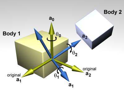
Figure 11: An AMotor joint with euler angles.
In this diagram, a0, a1 and a2 are the three axes along which angular motion is controlled. The green axes (including a0) are anchored to body 1. The blue axes (including a2) are anchored to body 2. To get the body 2 axes from the body 1 axes the following sequence of rotations is performed:
- Rotate by theta 0 about a0.
- Rotate by theta 1 about a1 (a1 has been rotated from its original position).
- Rotate by theta 2 about a2 (a2 has been rotated twice from its original position).
There is an important restriction when using euler angles: the theta 1 angle must not be allowed to get outside the range - pi /2 ... pi /2. If this happens then the AMotor joint will become unstable (there is a singularity at +/- pi /2). Thus you must set the appropriate stops on axis number 1.
void dJointSetAMotorMode (dJointID, int mode);
int dJointGetAMotorMode (dJointID);
Set (and get) the angular motor mode. The mode parameter must be one of the following constants:
| dAMotorUser | The AMotor axes and joint angle settings are entirely controlled by the user. This is the default mode. |
| dAMotorEuler | Euler angles are automatically computed. The axis a1 is also automatically computed. The AMotor axes must be set correctly when in this mode, as described below. When this mode is initially set the current relative orientations of the bodies will correspond to all euler angles at zero. |
void dJointSetAMotorNumAxes (dJointID, int num);
int dJointGetAMotorNumAxes (dJointID);
Set (and get) the number of angular axes that will be controlled by the AMotor. The argument num can range from 0 (which effectively deactivates the joint) to 3. This is automatically set to 3 in dAMotorEuler mode.
void dJointSetAMotorAxis (dJointID, int anum, int rel, dReal x, dReal y, dReal z);
void dJointGetAMotorAxis (dJointID, int anum, dVector3 result);
int dJointGetAMotorAxisRel (dJointID, int anum);
Set (and get) the AMotor axes. The anum argument selects the axis to change (0,1 or 2). Each axis can have one of three "relative orientation" modes, selected by rel:
- 0: The axis is anchored to the global frame.
- 1: The axis is anchored to the first body.
- 2: The axis is anchored to the second body.
The axis vector (x,y,z) is always specified in global coordinates regardless of the setting of rel. There are two GetAMotorAxis functions, one to return the axis and one to return the relative mode.
For dAMotorEuler mode:
- Only axes 0 and 2 need to be set. Axis 1 will be determined automatically at each time step.
- Axes 0 and 2 must be perpendicular to each other.
- Axis 0 must be anchored to the first body, axis 2 must be anchored to the second body.
void dJointSetAMotorAngle (dJointID, int anum, dReal angle);
Tell the AMotor what the current angle is along axis anum. This function should only be called in dAMotorUser mode, because in this mode the AMotor has no other way of knowing the joint angles. The angle information is needed if stops have been set along the axis, but it is not needed for axis motors.
dReal dJointGetAMotorAngle (dJointID, int anum);
Return the current angle for axis anum. In dAMotorUser mode this is simply the value that was set with dJointSetAMotorAngle. In dAMotorEuler mode this is the corresponding euler angle.
dReal dJointGetAMotorAngleRate (dJointID, int anum);
Return the current angle rate for axis anum. In dAMotorUser mode this is always zero, as not enough information is available. In dAMotorEuler mode this is the corresponding euler angle rate.
Linear Motor
A linear motor (LMotor) allows the relative linear velocities of two bodies to be controlled. The linear velocity can be controlled on up to three axes, allowing torque motors and stops to be set for translation along those axes (see the "Stops and motor parameters" section below).
void dJointSetLMotorNumAxes (dJointID, int num);
int dJointGetLMotorNumAxes (dJointID);
Set (and get) the number of axes that will be controlled by the LMotor. The argument num can range from 0 (which effectively deactivates the joint) to 3.
void dJointSetLMotorAxis (dJointID, int anum, int rel, dReal x, dReal y, dReal z);
void dJointGetLMotorAxis (dJointID, int anum, dVector3 result);
Set (and get) the LMotor axes. The anum argument selects the axis to change (0,1 or 2). Each axis can have one of three "relative orientation" modes, selected by rel:
- 0: The axis is anchored to the global frame.
- 1: The axis is anchored to the first body.
- 2: The axis is anchored to the second body.
The axis vector (x,y,z) is always specified in global coordinates regardless of the setting of rel.
Plane 2D
The plane-2d joint acts on a body and constrains it to the Z == 0 plane. Some drift may still occur due to numerical inaccuracies, so bodies must be reset after each frame using some code like this:
    const dReal     *rot = dBodyGetAngularVel (my_body.id()));
    const dReal     *quat_ptr;
    dReal           quat[4],
                    quat_len;
    quat_ptr = dBodyGetQuaternion (my_body.id()));
    quat[0] = quat_ptr[0];
    quat[1] = 0;
    quat[2] = 0;
    quat[3] = quat_ptr[3];
    quat_len = sqrt (quat[0] * quat[0] + quat[3] * quat[3]);
    quat[0] /= quat_len;
    quat[3] /= quat_len;
    dBodySetQuaternion (my_body.id()), quat);
    dBodySetAngularVel (my_body.id()), 0, 0, rot[2]);
Double Ball And Socket
The double ball joint (also known as a "distance joint") keeps two anchor points (one from each body) at a fixed distance apart. This distance is deduced by the relative positions of the anchor points during dJointAttach(), or can be set manually later.
TODO: add picture
void dJointSetDBallAnchor1(dJointID, dReal x, dReal y, dReal z);
void dJointSetDBallAnchor2(dJointID, dReal x, dReal y, dReal z);
void dJointGetDBallAnchor1(dJointID, dVector3 result);
void dJointGetDBallAnchor2(dJointID, dVector3 result);
Sets and gets the anchors. Anchor 1 is attached to body 1, anchor 2 is attached to body 2.
dReal dJointGetDBallDistance(dJointID);
Returns the target distance between the anchors. The actual distance between the anchors may differ due to joint errors.
void dJointSetDBallDistance(dJointID, dReal dist);
Manually sets the target distance the joint will try to maintain. This overrides the value automatically computed during dJointAttach().
Double Hinge
The Double Hinge joint is like the Hinge2 joint, but both axes are the same.
TODO: add picture
void dJointSetDHingeAxis(dJointID, dReal x, dReal y, dReal z);
void dJointGetDHingeAxis(dJointID, dVector3 result);
Sets and gets the axis for both hinges.
void dJointSetDHingeAnchor1(dJointID, dReal x, dReal y, dReal z);
void dJointSetDHingeAnchor2(dJointID, dReal x, dReal y, dReal z);
void dJointGetDHingeAnchor1(dJointID, dVector3 result);
void dJointGetDHingeAnchor2(dJointID, dVector3 result);
Sets and gets the anchors. Anchor 1 is attached to body 1, anchor 2 is attached to body 2.
dReal dJointGetDHingeDistance(dJointID);
Returns the distance between the anchors.
Transmission
The transmission joint transmits torque from one body to another. It works in 3 modes:
- Intersecting-axes: simulates intersecting-axes beveled gears
- Parallel-axes: simulates parallel-axes gears
- Chain-drive: simulate chain and sprockets
TODO: a picture is needed here
void dJointSetTransmissionMode( dJointID j, int mode );
int dJointGetTransmissionMode( dJointID j );
Set and get the mode of the transmission joint. mode can be one of:
- dTransmissionIntersectingAxes
- dTransmissionParallelAxes
- dTransmissionChainDrive
void dJointGetTransmissionContactPoint1(dJointID, dVector3 result);
void dJointGetTransmissionContactPoint2(dJointID, dVector3 result);
Gets the contact points for the first and second wheel.
void dJointSetTransmissionAxis1(dJointID, dReal x, dReal y, dReal z);
void dJointSetTransmissionAxis2(dJointID, dReal x, dReal y, dReal z);
void dJointGetTransmissionAxis1(dJointID, dVector3 result);
void dJointGetTransmissionAxis2(dJointID, dVector3 result);
Intersecting-axes mode: Sets and gets the axes for the first and second bodies.
void dJointSetTransmissionAnchor1(dJointID, dReal x, dReal y, dReal z);
void dJointSetTransmissionAnchor2(dJointID, dReal x, dReal y, dReal z);
void dJointGetTransmissionAnchor1(dJointID, dVector3 result);
void dJointGetTransmissionAnchor2(dJointID, dVector3 result);
Set and get the anchor points for each body.
void dJointSetTransmissionRatio( dJointID j, dReal ratio );
Parallel-axes mode only: Set the angular speed ratio between the gears. For the other modes the ratio is derived from the intersection angle or wheel radii.
dReal dJointGetTransmissionRatio( dJointID j );
Get the angular speed ratio between the gears.
void dJointSetTransmissionAxis( dJointID j, dReal x, dReal y, dReal z );
void dJointGetTransmissionAxis( dJointID j, dVector3 result );
Parallel-axes and chain-drive mode only. Set and get the axes used for both wheels.
dReal dJointGetTransmissionAngle1( dJointID j );
dReal dJointGetTransmissionAngle2( dJointID j );
Get the phase, that is the traversed angle for the first and second wheel.
dReal dJointGetTransmissionRadius1( dJointID j );
dReal dJointGetTransmissionRadius2( dJointID j );
Get the radius of each wheel of the joint.
void dJointSetTransmissionRadius1( dJointID j, dReal radius );
void dJointSetTransmissionRadius2( dJointID j, dReal radius );
Chain-drive mode only: set the radius of each wheel. The radii is implicit in the other modes.
void dJointSetTransmissionBacklash( dJointID j, dReal backlash );
dReal dJointGetTransmissionBacklash( dJointID j );
Set and get the backlash of the joint.
Backlash is the clearance in the mesh of the wheels of the transmission, and is defined as the maximum distance that the geometric contact point can travel without any actual contact or transfer of power between the wheels. This can be converted in radians of revolution for each wheel by dividing by the wheel's radius.
To further illustrate this consider the situation where a wheel of radius  is driving another wheel of radius
  and
there is an amount of backlash equal to
and
there is an amount of backlash equal to  in their mesh. If the driving wheel were to instantaneously stop there would be no
contact, and hence the driven wheel would continue to turn for another
in their mesh. If the driving wheel were to instantaneously stop there would be no
contact, and hence the driven wheel would continue to turn for another  radians until all the backlash in the mesh was taken
up and contact restored. The backlash is therefore given in untis of length.
radians until all the backlash in the mesh was taken
up and contact restored. The backlash is therefore given in untis of length.
General
The joint geometry parameter setting functions should only be called after the joint has been attached to bodies, and those bodies have been correctly positioned, otherwise the joint may not be initialized correctly. If the joint is not already attached, these functions will do nothing.
For the parameter getting functions, if the system is out of alignment (i.e. there is some joint error) then the anchor/axis values will be correct with respect to body 1 only (or body 2 if you specified body 1 as zero in the dJointAttach function).
The default anchor for all joints is (0,0,0). The default axis for all joints is (1,0,0).
When an axis is set it will be normalized to unit length. The adjusted axis is what the axis getting functions will return.
When measuring a joint angle or position, a value of zero corresponds to the initial position of the bodies relative to each other.
Note that there are no functions to set joint angles or positions (or their rates) directly, instead you must set the corresponding body positions and velocities.
Stops and motor parameters
When a joint is first created there is nothing to prevent it from moving through its entire range of motion. For example a hinge will be able to move through its entire angle, and a slider will slide to any length.
This range of motion can be limited by setting stops on the joint. The joint angle (or position) will be prevented from going below the low stop value, or from going above the high stop value. Note that a joint angle (or position) of zero corresponds to the initial body positions.
As well as stops, many joint types can have motors. A motor applies a torque (or force) to a joint's degree(s) of freedom to get it to pivot (or slide) at a desired speed. Motors have force limits, which means they can apply no more than a given maximum force/torque to the joint.
Motors have two parameters: a desired speed, and the maximum force that is available to reach that speed. This is a very simple model of real life motors, engines or servos. However, is it quite useful when modeling a motor (or engine or servo) that is geared down with a gearbox before being connected to the joint. Such devices are often controlled by setting a desired speed, and can only generate a maximum amount of power to achieve that speed (which corresponds to a certain amount of force available at the joint).
Motors can also be used to accurately model dry (or Coulomb) friction in joints. Simply set the desired velocity to zero and set the maximum force to some constant value - then all joint motion will be impeded by that force.
The alternative to using joint stops and motors is to simply apply forces to the affected bodies yourself. Applying motor forces is easy, and joint stops can be emulated with restraining spring forces. However applying forces directly is often not a good approach and can lead to severe stability problems if it is not done carefully.
Consider the case of applying a force to a body to achieve a desired velocity. To calculate this force  you use information about the current velocity, something like this:

This has several problems. First, the parameter must be tuned by hand. If it is too low the body will take a long time to come up to speed. If it is too high the simulation will become unstable. Second, even if is chosen well the body will still take a few time steps to come up to speed. Third, if any other "external" forces are being applied to the body, the desired velocity may never even be reached (a more complicated force equation would be needed, which would have extra parameters and its own problems).
Joint motors solve all these problems: they bring the body up to speed in one time step, provided that does not take more force than is allowed. Joint motors need no extra parameters because they are actually implemented as constraints. They can effectively see one time step into the future to work out the correct force. This makes joint motors more computationally expensive than computing the forces yourself, but they are much more robust and stable, and far less time consuming to design with. This is especially true with larger rigid body systems.
Similar arguments apply to joint stops.
Parameter Functions
Here are the functions that set stop and motor parameters (as well as other kinds of parameters) on a joint:
void dJointSetHingeParam (dJointID, int parameter, dReal value);
void dJointSetSliderParam (dJointID, int parameter, dReal value);
void dJointSetHinge2Param (dJointID, int parameter, dReal value);
void dJointSetUniversalParam (dJointID, int parameter, dReal value);
void dJointSetAMotorParam (dJointID, int parameter, dReal value);
void dJointSetLMotorParam (dJointID, int parameter, dReal value);
void dJointSetPRParam (dJointID, int parameter, dReal value);
void dJointSetPUParam (dJointID, int parameter, dReal value);
void dJointSetPistonParam (dJointID, int parameter, dReal value);
void dJointSetDBallParam(dJointID, int parameter, dReal value);
void dJointSetDHingeParam(dJointID, int parameter, dReal value);
void dJointSetTransmissionParam(dJointID, int parameter, dReal value);

dReal dJointGetHingeParam (dJointID, int parameter);
dReal dJointGetSliderParam (dJointID, int parameter);
dReal dJointGetHinge2Param (dJointID, int parameter);
dReal dJointGetUniversalParam (dJointID, int parameter);
dReal dJointGetAMotorParam (dJointID, int parameter);
dReal dJointGetLMotorParam (dJointID, int parameter);
dReal dJointGetPRParam (dJointID, int parameter);
dReal dJointGetPUParam (dJointID, int parameter);
dReal dJointGetPistonParam (dJointID, int parameter);
dReal dJointGetDBallParam(dJointID, int parameter);
dReal dJointGetDHingeParam(dJointID, int parameter);
dReal dJointGetTransmissionParam(dJointID, int parameter);
Set/get limit/motor parameters for each joint type. The parameter numbers are:
| dParamLoStop | Low stop angle or position. Setting this to -dInfinity (the default value) turns off the low stop.
For rotational joints, this stop must be greater than - pi to be effective. |
| dParamHiStop | High stop angle or position. Setting this to dInfinity (the default value) turns off the high stop. For rotational joints, this stop must be less than pi to be effective. If the high stop is less than the low stop then both stops will be ineffective. |
| dParamVel | Desired motor velocity (this will be an angular or linear velocity). |
| dParamFMax | The maximum force or torque that the motor will use to achieve the desired velocity. This must always be greater than or equal to zero. Setting this to zero (the default value) turns off the motor. |
| dParamFudgeFactor | The current joint stop/motor implementation has a small problem: when the joint is at one stop and the motor is set to move it away from the stop, too much force may be applied for one time step, causing a jumping motion. This fudge factor is used to scale this excess force. It should have a value between zero and one (the default value). If the jumping motion is too visible in a joint, the value can be reduced. Making this value too small can prevent the motor from being able to move the joint away from a stop. |
| dParamBounce | The bouncyness of the stops. This is a restitution parameter in the range 0..1. 0 means the stops are not bouncy at all, 1 means maximum bouncyness. |
| dParamCFM | The constraint force mixing (CFM) value used when not at a stop. |
| dParamStopERP | The error reduction parameter (ERP) used by the stops. |
| dParamStopCFM | The constraint force mixing (CFM) value used by the stops. Together with the ERP value this can be used to get spongy or soft stops. Note that this is intended for unpowered joints, it does not really work as expected when a powered joint reaches its limit. |
| dParamSuspensionERP | Suspension error reduction parameter (ERP). Currently this is only implemented on the hinge-2 joint. |
| dParamSuspensionCFM | Suspension constraint force mixing (CFM) value. Currently this is only implemented on the hinge-2 joint. |
If a particular parameter is not implemented by a given joint, setting it will have no effect and getting it will return 0.
Important: These parameter names can be optionally followed by a digit (2 or 3) to indicate the second or third set of parameters, e.g. for the second axis in a hinge-2 joint, or the third axis in an AMotor joint. A constant dParamGroup is also defined such that: dParamXi = dParamX + dParamGroup * (i-1)
The following table shows the valid parameter groups for each joint type.
| Joint Type | Number of Param Groups |
| Ball And Socket | 0 |
| Hinge | 1 |
| Slider | 1 |
| Contact | 0 |
| Universal | 2 |
| Fixed | 0 |
| Angular Motor | 3 |
| Linear Motor | 3 |
| Plane2D | 3 |
| Rotoide and Prismatic | 0 |
Setting Joint Torques/Forces Directly
Motors (see above) allow you to set joint velocities directly. However, you may instead wish to set the torque or force at a joint instead. These functions do just that. Note that they don't affect the motor, but simply call dBodyAddForce dBodyAddTorque on the bodies attached to it.
void dJointAddHingeTorque (dJointID, dReal torque);
Applies the torque about the hinge axis. That is, it applies a torque with magnitude torque, in the direction of the hinge axis, to body 1, and with the same magnitude but in opposite direction to body 2. This function is just a wrapper for dBodyAddTorque.
void dJointAddUniversalTorques (dJointID, dReal torque1, dReal torque2);
Applies torque1 about the universal's axis 1, and torque2 about the universal's axis 2. This function is just a wrapper for dBodyAddTorque.
void dJointAddSliderForce (dJointID, dReal force);
Applies the given force in the slider's direction. That is, it applies a force with magnitude force, in the direction slider's axis, to body1, and with the same magnitude but opposite direction to body2. This function is just a wrapper for dBodyAddForce.
void dJointAddHinge2Torques (dJointID, dReal torque1, dReal torque2);
Applies torque1 about the hinge2's axis 1, and torque2 about the hinge2's axis 2. This function is just a wrapper for dBodyAddTorque.
void dJointAddAMotorTorques (dJointID, dReal torque0, dReal torque1, dReal torque2);
Applies torque0 about the AMotor's axis 0, torque1 about the AMotor's axis 1, and torque2 about the AMotor's axis 2. If the motor has fewer than three axes, the higher torques are ignored. This function is just a wrapper for dBodyAddTorque.